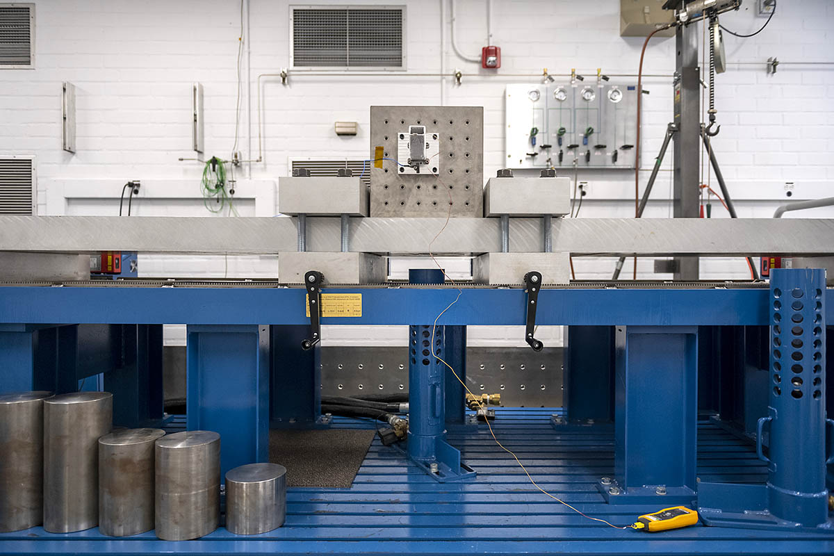
The shock for the test is generated by launching a steel mass (one of the round cylinders in the lower left of the image) into the bottom of the long steel beam. The large clamps set the length of the beam that can “ring” from the impact. By changing the clamp position the profile of the shock can be tuned, hence the name “tunable beam.” The large cube mounted to the beam simplifies mounting of hardware for testing. The shock event is captured using an accelerometer mounted at the hardware. (NASA/JPL-Caltech)
Home The shock for the test is generated by launching a steel mass (one of the round cylinders in the lower left of the image) into the bottom of the long steel beam. The large clamps set the length of the beam that can “ring” from the impact. By changing the clamp position the profile of the shock can be tuned, hence the name “tunable beam.” The large cube mounted to the beam simplifies mounting of hardware for testing. The shock event is captured using an accelerometer mounted at the hardware. (NASA/JPL-Caltech) The shock for the test is generated by launching a steel mass (one of the round cylinders in the lower left of the image) into the bottom of the long steel beam. The large clamps set the length of the beam that can “ring” from the impact. By changing the clamp position the profile of the shock can be tuned, hence the name “tunable beam.” The large cube mounted to the beam simplifies mounting of hardware for testing. The shock event is captured using an accelerometer mounted at the hardware. (NASA/JPL-Caltech)
The shock for the test is generated by launching a steel mass (one of the round cylinders in the lower left of the image) into the bottom of the long steel beam. The large clamps set the length of the beam that can “ring” from the impact. By changing the clamp position the profile of the shock can be tuned, hence the name “tunable beam.” The large cube mounted to the beam simplifies mounting of hardware for testing. The shock event is captured using an accelerometer mounted at the hardware. (NASA/JPL-Caltech)